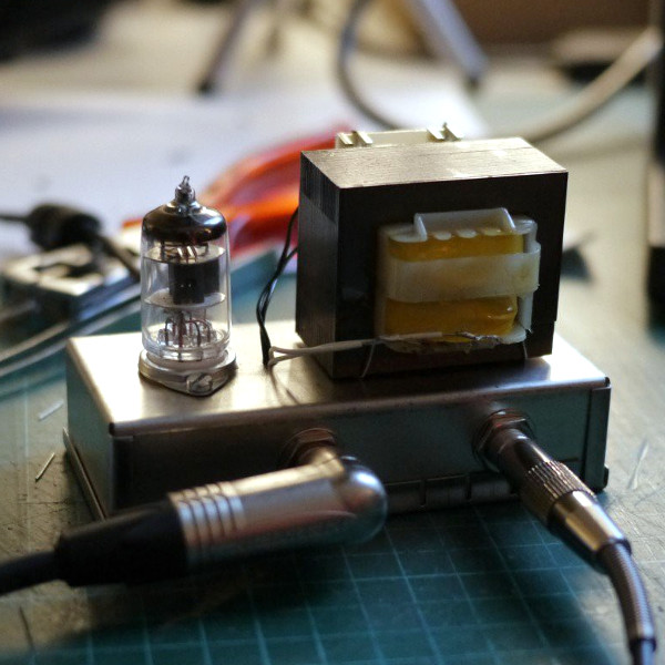
At the extreme budget end of tube audio lie single-tube amplifiers usually using very cheap small-signal pentodes. They’ve appeared here before in various guises, and a fitting addition to those previous projects comes from [Kris Slyka]. It’s a classic circuit with a transformer output, and it provides enough amplification to drive a pair of headphones or even a speaker at low levels.
Most tube enthusiasts will instantly recognize the anode follower circuit with a transformer in the anode feed through which the output is taken. The tube works in Class A, which means that it’s in its least efficient mode but the one with the least distortion. The transformer itself isn’t an audio part, but a small mains transformer taken from a scrap wall wart. It serves not only for isolation, but also to transform the high impedance output from the tube into a low impedance suitable for driving a headphone or speaker.
The HT voltage is a relatively low 24 V, but it still manages to drive headphones acceptably. Speaker levels require a pre-amp, but even then it’s likely that this circuit is pushing the tube beyond what it’s capable of with a speaker. The more it operates towards the edge of its performance envelope the more distortion it will generate and the worse a sound it will produce. This isn’t such a problem in a guitar application as here, but hi-fi enthusiasts may find it to be too much. It would be interesting to subject it as a headphone amplifier to a series of audio tests to evaluate the effect of a mains transformer over a dedicated audio one.
A Tiny Tube Amp For Not A Lot
Last year we took a very in-depth look at the commonly-available Chinese kit pre-amps that use a similar anode-follower circuit but without the transformer. We’ve also seen a similar amp that uses an op-amp as an impedance converter, as well as a novel take on the idea whose unusual biasing allows it to run from only 3.3 volts. These circuits can be so cheap to get started with that we’d suggest anyone give them a try.I started playing guitar in my teens, and saw DIY as an opportunity to build all the pedals that I could not afford at the time. I have built several mini amplifiers using sub-miniature tubes, but mostly they are still too loud to play in an apartment, and still require a lot of power just to heat up and power up the switched-mode power supply (SMPS) which multiplies the voltage, from 12 V to 200 V. I always wanted to build a battery-powered tube amplifier for the guitar, like some old radios, but wanted to use the current available LiPo batteries; much easier to recharge than the old 45 V batteries.
So, first I tested if the SMPS that I was currently using could work at lower input voltages. 3.7 V in this case was not enough, so I used two batteries in series, and that worked up to 150 V. The tubes I found while looking for battery tubes. There is an article about the 1J24b, stating that, with a much lower filament, it could deliver the same amplification as the DF96, making this tube the best gain/consumption tube available. For the power stage, I chose the 1J29b, from the same family of Russian tubes with lower filament currents.
DIY smart camera Combine the power and versatility of a Raspberry Pi single-board computer with an off-the-shelf camera module and you can do great things. We’ll show you how to automatically take…
Build Your Own Diy Guitar Amp From Scratch
The amplifier is composed of two main stages: a paraphase phase inverter, and a push-pull output stage. I used a 100 V line transformer as the output transformer, to keep the cost low, and to achieve the high primary impedance required by the output tubes. A proper transformer would be at least two times bigger, and would cost at least four times more than this one.
Print subscriptions to magazine start from just £4, saving you a big chunk of money on the cover price. You’ll get exclusive subscriber offers, and more projects, ideas, and inspiration than you can shake a toolbox at. Upgrade your ideas — subscribe to magazine!In this project article for , the author shares his guitar tube amplifier, a simple, low-wattage, that any DIYer can easily build. Costas Sarris believes in building simple tube amplifier designs, with simple circuits that he found to work better, particularly when the electric signals carry music information, because the signal distortion is easily handled. This article was originally published in , June 2015.
When a guitarist friend urged me to build a guitar tube amplifier, we agreed that the amplifier design should be a simple, low-wattage single-ended amplifier—built much like a Swiss army knife—for everyday use. Inspired by late 1950s Fender “Princeton” and “Champ” amplifier designs, I decided to construct a small but efficient single-ended head amplifier, that any DIYer could easily build (see Photo 1).
Best Tube Amps Under $1,000
This small amplifier is a medium/high gained head, meant to be played at room or studio levels. Although it can get pretty loud, it can also be played with smooth bass and “quiet drums” on small stages.

Because of its warm sound, the amplifier isn’t made for any kind of hard metal music. On the other hand it is ideal for blues, rock, jazz, or funk music. The essence of this amplifier is simplicity. That’s what makes it different (see Photo 2).
The music information generated as an electric signal by an electric guitar pickup is weak and needs amplification. Guitar pickups have different output voltages depending on the model. Low-output models tend to produce a “clean” sound, while high-output models tend to overdrive amplifiers and produce a “dirty and aggressive sound.” The output voltage of most pickups varies between 100 mV and 1 VRMS.
Pairing Amps For Golden Tones
This amplifier uses the high gain 12AX7/ECC83 double triode vacuum tube for the preamp stage, and the 6L6GC beam power tube for the output stage in a single-ended Class-A design.
Class-A amps are voltage amplifiers. In a Class-A amplifier the output voltage’s wave shape is the same with the shape of the signal voltage applied to the grid. In other words, the power tube runs at full power all the time and that affects the way the output tube distorts. A Class-A power amplifier typically sounds warm and natural. When it tends to clip, it sounds dynamic and aggressive. That’s the reason these amplifiers are desirable for many guitarists.

The preamp stage uses a high gain 12AX7/ECC83 dual triode vacuum tube, and operates as a grounded cathode amplifier. The output is taken from the second half of the 12AX7 triode plate to the power tube’s grid, using a high-quality coupling capacitor 0.1 µF. The driver tube is cathode biased with a 1.5kΩ resistor (R8, R2 shown in Figure 1), and a 200V plate voltage (both stages).
How To Make A Guitar Amplifier From An Old Tube Radio
The preamplifier’s first half stage is a fully bypassed cathode bias circuit. The input grid-stopper resistor R12 is 33 kΩ. To bypass the cathode resistor in the first stage (the first half triode), I used a 25µF/25V audio electrolytic capacitor (C2 shown in Figure 1).
The gain potentiometer (1 MΩ) acts as a variable grid resistor to the grid of the second half of the 12AX7 preamp tube. The tone control section consists of a simple “tone boost control” circuit. C6 is the treble-shunt capacitor, so P2 (the tone control pot) affects both the ”tone cut” and the boost. The amount of boost depends on the gain pot’s setting. Tweaking the gain, you can adjust the amount of distortion you want.
The second half of the triode stage can be with or without a cathode bypass capacitor. Decreasing the cathode bypass capacitor’s size, improves the amplifier’s transient response.

Small Tube Guitar Amplifier
While the power tube cathode resistor is fully bypassed (C1, 25 µF/25 V), the power stage needs about a 20-V signal amplitude to be driven to full power. In this circuit, the grid resistor is a variable resistor (1 MΩ master volume pot). So if we use a small size (e.g., 1, 000 pF) cathode bypass capacitor in the preamplifier’s second stage, the amplifier’s input sensitivity—with the master volume pot fully open (1 MΩ) — is only 15 mV. That means we only need a 15 mV input to overdrive the power stage! Using a high-output guitar pickup, we can easily overdrive the amplifier to produce the desired “aggressive sound.” Increasing or decreasing the cathode bypass capacitance in the second half of the driver stage, we can improve the tone response, according to our individual taste.
In this project, the 6L6GC power tube is running at a 58 mA plate current when no signal is applied, and a 350V plate voltage. The output transformer’s primary impedance 4.5 kΩ. The power tube cathode resistor is fully bypassed by a 25 µf/25V capacitor (C1). The input grid-stopper resistor is 1 kΩ (R1). The voltage across the cathode resistor is measured at 19.5V.
One of the most critical components in the sound path is the output transformer. Therefore, you should never compromise on the output transformer’s quality.
Best Acoustic Guitar Amps 2023 (all Budgets)
For this amplifier, I chose a custom-made, “E”

0 Response to "Diy Small Guitar Tube Amp"
Posting Komentar